Product Description
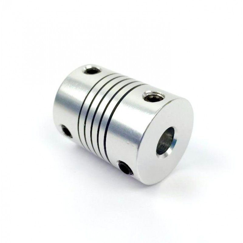
Drum Gear Coupling Shaft Coupling (GIICL)
GIICL type – the sealing end for the entire body, small spacing between the teeth, the relative allowable radial displacement, compact structure, small moment of inertia, can be connected with the Y, J1 type shaft.
Characteristics of drum type gear coupling:
1.drum tooth type coupling bearing capacity
2.angular displacement compensation
3.drumgear coupling drum tooth surface contact condition of inner and outer teeth are improved, to avoid the angular displacement under the condition of straight tooth end edge extrusion, stress measuringmethods concentration, while improving the tooth surface friction, wear, reducing noise and long maintenance cycle.
4.drum shaped teeth type shaft coupling gear tooth end is CHINAMFG shape, so that the inner and outer teeth are very convenient to install and remove.
5.drum gear type coupling transmission efficiency as high as 99.7%.
<table border="0" cellpadding="/8822 0571 1.75
Detailed Photos
Company Profile
HangZhou CHINAMFG Machinery Manufacturing Co., Ltd. is a high-tech enterprise specializing in the design and manufacture of various types of coupling. There are 86 employees in our company, including 2 senior engineers and no fewer than 20 mechanical design and manufacture, heat treatment, welding, and other professionals.
Advanced and reasonable process, complete detection means. Our company actively introduces foreign advanced technology and equipment, on the basis of the condition, we make full use of the advantage and do more research and innovation. Strict to high quality and operate strictly in accordance with the ISO9000 quality certification system standard mode.
Our company supplies different kinds of products. High quality and reasonable price. We stick to the principle of “quality first, service first, continuous improvement and innovation to meet the customers” for the management and “zero defect, zero complaints” as the quality objective.
Our Services
1. Design Services
Our design team has experience in Cardan shafts relating to product design and development. If you have any needs for your new product or wish to make further improvements, we are here to offer our support.
2. Product Services
raw materials → Cutting → Forging →Rough machining →Shot blasting →Heat treatment →Testing →Fashioning →Cleaning→ Assembly→Packing→Shipping
3. Samples Procedure
We could develop the sample according to your requirement and amend the sample constantly to meet your need.
4. Research & Development
We usually research the new needs of the market and develop new models when there are new cars in the market.
5. Quality Control
Every step should be a particular test by Professional Staff according to the standard of ISO9001 and TS16949.
FAQ
Q 1: Are you a trading company or a manufacturer?
A: We are a professional manufacturer specializing in manufacturing
various series of couplings.
Q 2:Can you do OEM?
Yes, we can. We can do OEM & ODM for all customers with customized PDF or AI format artwork.
Q 3:How long is your delivery time?
Generally, it is 20-30 days if the goods are not in stock. It is according to quantity.
Q 4: Do you provide samples? Is it free or extra?
Yes, we could offer the sample but not for free. Actually, we have an excellent price principle, when you make the bulk order the cost of the sample will be deducted.
Q 5: How long is your warranty?
A: Our Warranty is 12 months under normal circumstances.
Q 6: What is the MOQ?
A: Usually our MOQ is 1pcs.
Q 7: Do you have inspection procedures for coupling?
A:100% self-inspection before packing.
Q 8: Can I have a visit to your factory before the order?
A: Sure, welcome to visit our factory.
Q 9: What’s your payment?
A:1) T/T.
♦Contact Us
Web: huadingcoupling
Add: No.11 HangZhou Road,Chengnan park,HangZhou City,ZheJiang Province,China
/* January 22, 2571 19:08:37 */!function(){function s(e,r){var a,o={};try{e&&e.split(“,”).forEach(function(e,t){e&&(a=e.match(/(.*?):(.*)$/))&&1
Can Motor Couplings Compensate for Angular, Parallel, and Axial Misalignments?
Yes, motor couplings are designed to compensate for different types of misalignments, including angular, parallel, and axial misalignments. The ability to accommodate misalignment is a key feature of motor couplings, and various coupling types offer different levels of misalignment compensation:
1. Angular Misalignment:
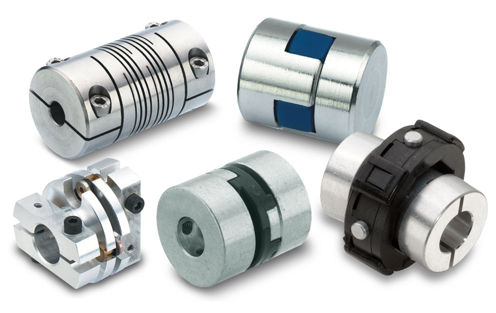
Angular misalignment occurs when the motor and driven equipment shafts are not perfectly aligned in the same plane, causing an angle between them. Motor couplings, especially flexible couplings, can effectively compensate for angular misalignment. Flexible couplings like jaw couplings, beam couplings, and oldham couplings can tolerate angular misalignment to a certain extent while transmitting torque smoothly.
2. Parallel Misalignment:
Parallel misalignment happens when the motor and driven equipment shafts are not perfectly aligned along their axis, leading to offset displacement. Flexible couplings, such as bellows couplings and disc couplings, are well-suited to accommodate parallel misalignment. These couplings can maintain good misalignment tolerance while providing high torsional stiffness for efficient torque transmission.
3. Axial Misalignment:
Axial misalignment occurs when there is a linear offset between the motor and driven equipment shafts along the axis. For some flexible couplings, a limited amount of axial misalignment can be tolerated. However, specific coupling types, such as self-aligning ball bearing couplings, are more suitable for handling higher levels of axial misalignment.
It is important to note that while motor couplings can compensate for misalignment, they have their limits. Excessive misalignment can lead to premature wear, reduced efficiency, and potential coupling failure. Proper alignment during installation and regular maintenance are essential to ensure the coupling’s misalignment compensation remains effective over time.
When selecting a motor coupling, consider the type and amount of misalignment expected in your application. Choose a coupling that offers the required level of misalignment compensation, ensuring smooth power transmission and extending the lifespan of the coupling and connected components.
“`
Temperature and Speed Limits for Different Motor Coupling Types
Motor couplings come in various types, and each type has its temperature and speed limits. These limits are essential considerations to ensure the coupling operates safely and efficiently. Here are the general temperature and speed limits for different motor coupling types:
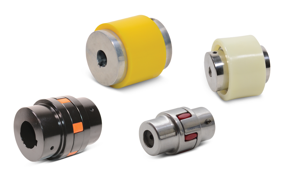
1. Elastomeric Couplings:
Elastomeric couplings, such as jaw couplings and spider couplings, are commonly used in a wide range of applications. They typically have temperature limits of approximately -40°C to 100°C (-40°F to 212°F). The speed limits for elastomeric couplings typically range from 3,000 to 6,000 RPM, depending on the specific coupling design and size.
2. Gear Couplings:
Gear couplings are known for their high torque capacity and durability. The temperature limits for gear couplings are usually between -50°C to 150°C (-58°F to 302°F). The speed limits for gear couplings can be as high as 5,000 to 10,000 RPM or more, depending on the size and design.
3. Disc Couplings:
Disc couplings provide high torsional stiffness and are often used in precision applications. The temperature limits for disc couplings are typically around -40°C to 200°C (-40°F to 392°F). The speed limits for disc couplings can range from 5,000 to 20,000 RPM or more.
4. Grid Couplings:
Grid couplings are known for their shock absorption capabilities. The temperature limits for grid couplings are usually between -30°C to 100°C (-22°F to 212°F). The speed limits for grid couplings typically range from 3,600 to 5,000 RPM.
5. Oldham Couplings:
Oldham couplings are often used to transmit motion between shafts with significant misalignment. The temperature limits for Oldham couplings are generally around -30°C to 80°C (-22°F to 176°F). The speed limits for Oldham couplings are usually up to 3,000 to 5,000 RPM.
6. Diaphragm Couplings:
Diaphragm couplings are suitable for applications requiring high precision and torque transmission. The temperature limits for diaphragm couplings are typically between -50°C to 300°C (-58°F to 572°F). The speed limits for diaphragm couplings can be as high as 10,000 to 30,000 RPM.
It is essential to check the manufacturer’s specifications and recommendations for the specific coupling model to ensure the coupling operates within its intended temperature and speed limits. Operating the coupling beyond these limits may lead to premature wear, reduced performance, or even catastrophic failure. Properly selecting a coupling that matches the application’s temperature and speed requirements is critical for reliable and safe operation.
“`
Can a Damaged Motor Coupling Lead to Motor or Equipment Failure?
Yes, a damaged motor coupling can lead to motor or equipment failure if not addressed promptly. Motor couplings play a critical role in connecting the motor to the driven equipment and transmitting torque between them. When a coupling is damaged, several potential issues can arise:
- Reduced Torque Transmission: Cracks, wear, or deformation in the coupling can result in reduced torque transmission from the motor to the driven equipment. This may lead to inefficient operation and underperformance of the machinery.
- Mechanical Vibrations: Damaged couplings can introduce vibrations into the system, leading to increased wear and fatigue on connected components, such as bearings and shafts. Excessive vibrations can cause premature failure of these parts.
- Misalignment and Stress: If the coupling loses its ability to compensate for misalignment, it can subject the motor and driven equipment to increased stress and loading. This can result in premature wear and failure of bearings, shafts, and other components.
- Overload on the Motor: In certain coupling designs, damage may result in a loss of overload protection. Without the safety mechanism, the motor may experience excessive loads, leading to overheating and possible motor failure.
- Increased Downtime: A damaged coupling can cause unexpected breakdowns and unplanned downtime for repairs, affecting productivity and overall operational efficiency.
- Safety Risks: In extreme cases, a severely damaged coupling may disintegrate during operation, posing safety risks to personnel and surrounding equipment.
To avoid motor or equipment failure due to a damaged coupling, regular maintenance and inspection are crucial. Visual inspections, vibration analysis, and monitoring of coupling performance can help identify signs of damage early on. If any issues are detected, it is essential to replace or repair the damaged coupling promptly to prevent further damage and ensure the reliable operation of the machinery.
Proper selection of high-quality couplings, appropriate for the specific application and operating conditions, can also reduce the likelihood of coupling failure and its potential impact on the motor and equipment.
“`

editor by CX 2024-04-16