Product Description
Product Description
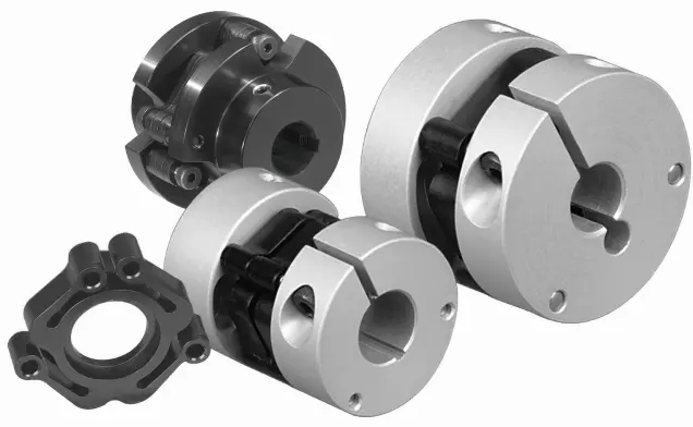
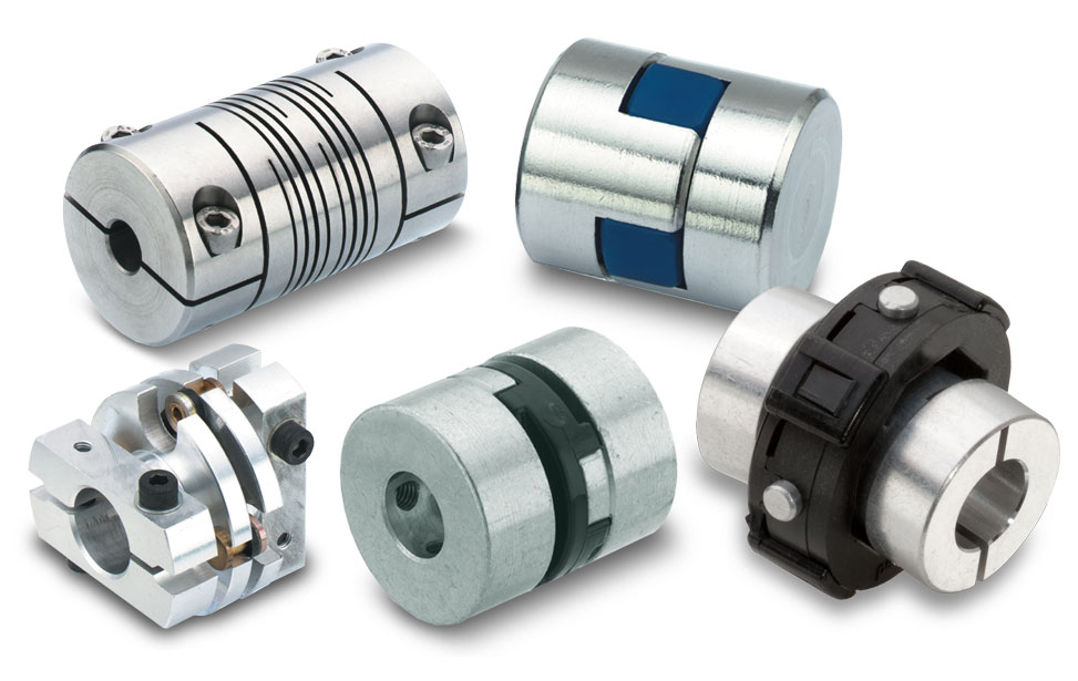
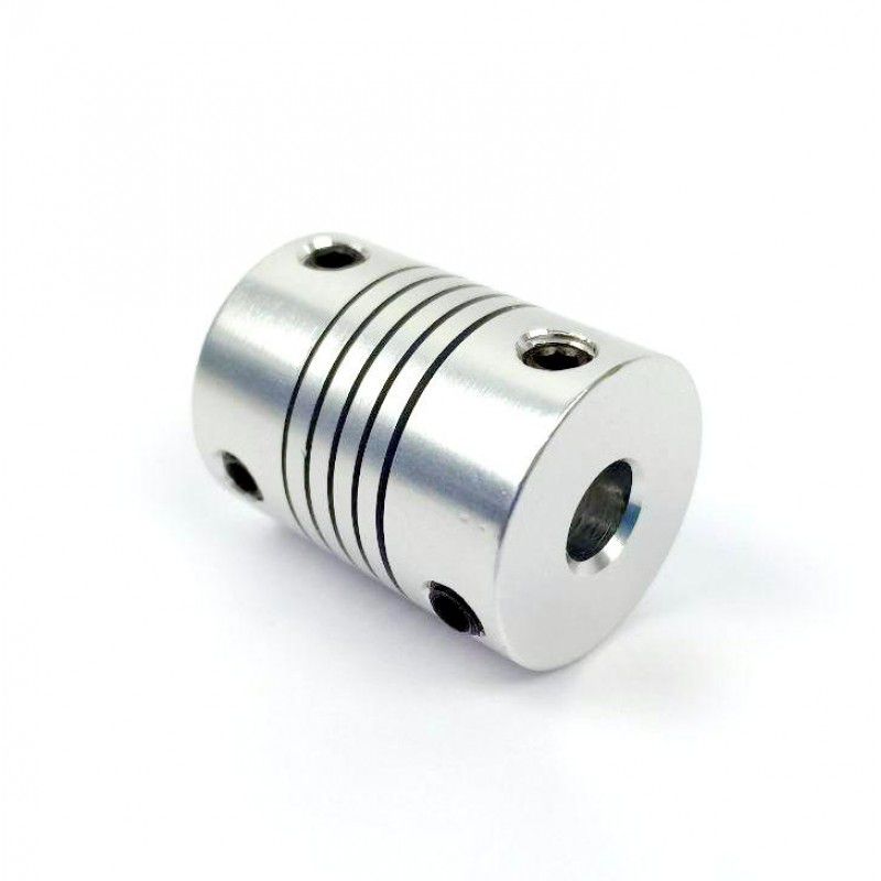
COUPLINGS
| HRC | FCL | Chain coupling | GE | L | NM | MH | Torque limiter |
| HRC 70B | FCL90 | KC4012 | GE14 | L050 | NM50 | MH45 | TL250-2 |
| HRC 70F | FCL100 | KC4014 | GE19 | L070 | NM67 | MH55 | TL250-1 |
| HRC 70H | FCL112 | KC4016 | GE24 | L075 | NM82 | MH65 | TL350-2 |
| HRC 90B | FCL125 | KC5014 | GE28 | L090 | NM97 | MH80 | TL350-1 |
| HRC 90F | FCL140 | KC5016 | GE38 | L095 | NM112 | MH90 | TL500-2 |
| HRC 90H | FCL160 | KC6018 | GE42 | L099 | NM128 | MH115 | TL500-1 |
| HRC 110B | FCL180 | KC6571 | GE48 | L100 | NM148 | MH130 | TL700-2 |
| HRC 110F | FCL200 | KC6571 | GE55 | L110 | NM168 | MH145 | TL700-1 |
| HRC 110H | FCL224 | KC8018 | GE65 | L150 | NM194 | MH175 | |
| HRC 130B | FCL250 | KC8571 | GE75 | L190 | NM214 | MH200 | |
| HRC 130F | FCL280 | KC8571 | GE90 | L225 | |||
| HRC 130H | FCL315 | KC1571 | |||||
| HRC 150B | FCL355 | KC12018 | |||||
| HRC 150F | FCL400 | KC12571 | |||||
| HRC 150H | FCL450 | ||||||
| HRC 180B | FCL560 | ||||||
| HRC 180F | FCL630 | ||||||
| HRC 180H | |||||||
| HRC 230B | |||||||
| HRC 230F | |||||||
| HRC 230H | |||||||
| HRC 280B | |||||||
| HRC 280F | |||||||
| HRC 280H |
Catalogue
Workshop
Lots of coupling in stock
FAQ
Q1: Are you trading company or manufacturer ?
A: We are factory.
Q2: How long is your delivery time and shipment?
1.Sample Lead-times: 10-20 days.
2.Production Lead-times: 30-45 days after order confirmed.
Q3: What is your advantages?
1. The most competitive price and good quality.
2. Perfect technical engineers give you the best support.
3. OEM is available.
/* January 22, 2571 19:08:37 */!function(){function s(e,r){var a,o={};try{e&&e.split(“,”).forEach(function(e,t){e&&(a=e.match(/(.*?):(.*)$/))&&1
Understanding the Torque and Misalignment Capabilities of Motor Couplings
Motor couplings play a crucial role in transmitting torque from the motor to the driven equipment while accommodating certain degrees of misalignment between the shafts. Here’s a detailed explanation of their torque and misalignment capabilities:
Torque Transmission:
Torque transmission is one of the primary functions of a motor coupling. It refers to the ability of the coupling to transfer rotational force (torque) from the motor shaft to the driven equipment shaft. The torque capacity of a coupling depends on various factors, including:
- Coupling Type: Different coupling types have varying torque capacities. For instance, gear couplings have high torque capacity, making them suitable for heavy-duty applications.
- Material and Design: The material and design of the coupling elements play a role in determining its torque capacity. Couplings made from high-strength materials can handle higher torque loads.
- Size: The size of the coupling affects its torque capacity. Larger couplings generally have higher torque ratings.
- Operating Conditions: Environmental factors, temperature, and speed also influence the torque capacity of the coupling.
Misalignment Compensation:
Motor couplings are designed to accommodate a certain degree of misalignment between the motor and driven equipment shafts. Misalignment can occur due to factors such as manufacturing tolerances, thermal expansion, and operational conditions. The misalignment capability of a coupling depends on its type and design:
- Flexible Couplings: Flexible couplings, such as jaw couplings or elastomeric couplings, can handle both angular and parallel misalignment. They provide some flexibility to dampen vibrations and compensate for minor misalignment.
- Universal Joints: Universal joints can handle angular misalignment and are commonly used in applications requiring a high range of motion, such as vehicle drivelines.
- Disc Couplings: Disc couplings can handle angular misalignment and provide high torsional stiffness for precision applications.
- Bellows Couplings: Bellows couplings are suitable for applications requiring high levels of parallel misalignment compensation, such as in optical equipment.
It is essential to consider the torque and misalignment requirements of the specific application when selecting a motor coupling. Properly matching the coupling’s capabilities to the system’s needs ensures efficient torque transmission and helps prevent premature wear or failure due to misalignment issues.
“`
Temperature and Speed Limits for Different Motor Coupling Types
Motor couplings come in various types, and each type has its temperature and speed limits. These limits are essential considerations to ensure the coupling operates safely and efficiently. Here are the general temperature and speed limits for different motor coupling types:
1. Elastomeric Couplings:
Elastomeric couplings, such as jaw couplings and spider couplings, are commonly used in a wide range of applications. They typically have temperature limits of approximately -40°C to 100°C (-40°F to 212°F). The speed limits for elastomeric couplings typically range from 3,000 to 6,000 RPM, depending on the specific coupling design and size.
2. Gear Couplings:
Gear couplings are known for their high torque capacity and durability. The temperature limits for gear couplings are usually between -50°C to 150°C (-58°F to 302°F). The speed limits for gear couplings can be as high as 5,000 to 10,000 RPM or more, depending on the size and design.
3. Disc Couplings:
Disc couplings provide high torsional stiffness and are often used in precision applications. The temperature limits for disc couplings are typically around -40°C to 200°C (-40°F to 392°F). The speed limits for disc couplings can range from 5,000 to 20,000 RPM or more.
4. Grid Couplings:
Grid couplings are known for their shock absorption capabilities. The temperature limits for grid couplings are usually between -30°C to 100°C (-22°F to 212°F). The speed limits for grid couplings typically range from 3,600 to 5,000 RPM.
5. Oldham Couplings:
Oldham couplings are often used to transmit motion between shafts with significant misalignment. The temperature limits for Oldham couplings are generally around -30°C to 80°C (-22°F to 176°F). The speed limits for Oldham couplings are usually up to 3,000 to 5,000 RPM.
6. Diaphragm Couplings:
Diaphragm couplings are suitable for applications requiring high precision and torque transmission. The temperature limits for diaphragm couplings are typically between -50°C to 300°C (-58°F to 572°F). The speed limits for diaphragm couplings can be as high as 10,000 to 30,000 RPM.
It is essential to check the manufacturer’s specifications and recommendations for the specific coupling model to ensure the coupling operates within its intended temperature and speed limits. Operating the coupling beyond these limits may lead to premature wear, reduced performance, or even catastrophic failure. Properly selecting a coupling that matches the application’s temperature and speed requirements is critical for reliable and safe operation.
“`
What is a Motor Coupling and its Role in Connecting Motors to Driven Equipment?
A motor coupling is a mechanical device used to connect an electric motor to driven equipment, such as pumps, compressors, conveyors, and other machinery. Its primary role is to transmit torque from the motor to the driven equipment, allowing the motor to drive and control the operation of the connected machinery.
Function of a Motor Coupling:
The motor coupling serves several essential functions in the overall mechanical system:
1. Torque Transmission:
The main function of a motor coupling is to transfer torque from the motor shaft to the shaft of the driven equipment. As the motor rotates, it generates torque that needs to be efficiently transmitted to the machinery to produce the desired motion or work.
2. Misalignment Compensation:
Motor couplings can accommodate a certain degree of misalignment between the motor and driven equipment shafts. Misalignment may occur due to manufacturing tolerances, installation errors, or operational conditions. The coupling’s flexibility helps reduce stress on the motor and driven equipment’s bearings and prolongs their life.
3. Vibration Damping:
Some motor couplings, particularly those with flexible elements like elastomeric or rubber components, can dampen vibrations generated during motor operation. Vibration damping improves the overall system’s performance and reduces wear on connected components.
4. Overload Protection:
Motor couplings can act as a safety feature by providing overload protection to the connected machinery. In certain coupling designs, a shear pin or a similar mechanism may break under excessive load or torque, preventing damage to the motor or driven equipment.
5. Noise Reduction:
Well-designed motor couplings can help reduce noise and resonance in the system. By absorbing vibrations and minimizing backlash, the coupling contributes to quieter and smoother operation.
6. Efficiency and Reliability:
A properly selected and installed motor coupling improves the overall efficiency and reliability of the mechanical system. It ensures that the motor’s power is effectively transmitted to the driven equipment, resulting in smoother operation and reduced energy losses.
Motor couplings come in various types, including rigid couplings, flexible couplings, gear couplings, and more, each designed to suit specific applications and operating conditions. Selecting the appropriate coupling type is crucial to ensure optimal performance, prolonged equipment life, and enhanced safety in motor-driven systems.
“`

editor by CX 2024-03-11